2.0 New Body Leaning CountersteerS (BLCs) Theory
Since the ‘celerifere’ and the ‘draisienne’, millions of people have imagined theories explaining the stability and steering of 2-Wheelers.
But somehow, even the well known 2-Wheeler steering theories (Counter-steering, Gyroscopic reactions, Front fork geometry …) have limits that support misunderstandings. They do not bring up a consensus among cyclists and even scientific background people. This certainly doesn’t help avoid motorcycle accidents.
The new steering theory explained on this site does not contradict the contribution of these other known theories, but:
- It completes them and puts them in perspective, to explain better how motorcycles and bicycles stay upright and ride so well.
- It improves the countersteering technique and increases steering precision and riding safety.
- And it helps analyze and develop safer and more comfortable motorcycle concepts.
This Body Leaning CountersteerS (BLCs) theory is based on recognition of the Torso-Arms-Handlebar mechanism (TAHm). Click on the following links to know more:
2.1 The Torso-Arms-Handlebar mechanism (TAHm)
2.2 Where stability comes from at slow speeds
2.3 Three steps when going into a turn
2.4 The Body Leaning CountersteerS (BLCs) theory is based on Scientific Principles and on Servomechanism Theory
2.4.1 Mechanical Engineering Theses
2.4.2 Understanding the hidden steering servomechanism of the Body Leaning CountersteerS theory
2.4.3 Which Torso-Arms-Handlebar geometries work best or worst
2.4.4 Where does the steering servomechanism damping come from
2.4.5 The global system including the rider and 2-Wheeler in the road environment
2.1 The Torso-Arms-Handlebar mechanism (TAHm):

According to the Body Leaning CountersteerS (BLCs) theory, the torso, the arms and the handlebar constitute a mechanism:
It’s not so obvious, but the rider’s torso leaning right or left controls the orientation of the handlebar in a peculiar way.
If the torso leans to one side, the handlebar is oriented towards the opposite direction, simply because one arm pushes on one side while the other pulls on the other side of the handlebar.
The rider can fool this mechanism and the arms or elbows may flex, but the mechanism is natural, basic, smooth and proportional. The more you lean, the more the handlebar is oriented towards the opposite direction. During normal riding, the handlebar is not being pushed in a jerky fashion and the mechanism acts automatically without being noticed.
Furthermore, the rider can and does learn to modify this mechanism, exactly as a real electric or hydraulic servomechanism can have a PID (Proportional-Differential-Integral) correction mechanism, to make it faster and more precise.
For instance on a mountain bike going uphill at very slow speed, the rider progressively learns to steer stronger than normal on the handlebar, when he feels that he’s going to fall. And this saves him from falling even at very low speeds, so he can keep on pedalling… and sometimes win a race…
2.2 Where stability comes from at slow speeds:
If a 2-Wheeler is moving forward as in (A), it may fall to one side as in (B). But the rider does not want to fall and stays up along the vertical gray line as in (C). So as in (D), one arm automatically pushes and the other pulls the handlebar towards where the 2-Wheeler falls, in the direction of the small black arrows. So the front wheel is oriented in the direction of the Bigger black arrow as in (E). And this generates a centrifugal force along the red arrow, which brings the 2-Wheeler back to the vertical as in (F).
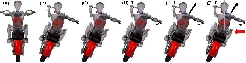
Note: It is in the 2-Wheeler’s system of reference, that this centrifugal force in the direction of the red arrow is felt. Looking at the 2-Wheeler from the exterior, it rather is the front tire ground-contact-point that goes to the right under the vehicle to bring it back up. This is exactly as the finger under a vertical broom: If the supporting finger moves to the right, the broom falls to the left.
More information can be found on this in Mr. Tony Foale’s book: Motorcycle Handling and Chassis Design and on his site at: www.tonyfoale.com
This works on both sides so that the 2-Wheeler is stable. Thus, the surprising existence of this mechanism renders 2-Wheelers stable, even at slow speeds and without any special equilibrium skill. By contrast, only a minority of humans can remain upright on a 2-Wheeler at stand-still or on a monocycle, where the Torso-Arms-Handlebar mechanism is ineffective.
2.3 Three steps when going into a turn
According to the Body Leaning CountersteerS (BLCs) theory, going into a turn can be broken down into three main steps for a better illustration of what happens dynamically:

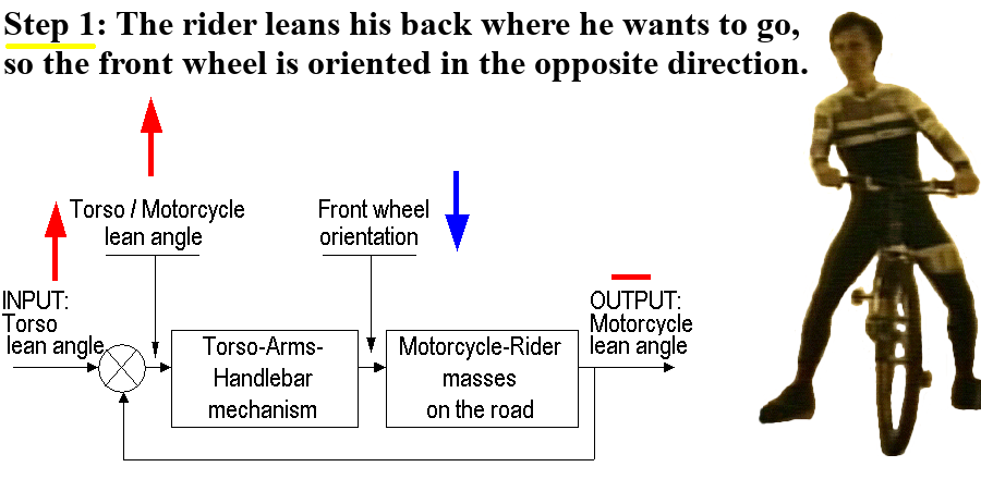
Step 1: If the rider’s torso suddenly leans to its right, for instance, the 2-Wheeler leans to the left in reaction. So the front wheel is unconsciously oriented to the left by the Torso-Arms-Handlebar mechanism (short black line under the front wheel). The front wheel orientation generates a centrifugal force, or the tire-ground contact patch rapidly moves to the left, so that the 2-Wheeler is pushed to its right.
Please note that the front wheel may also be oriented to the left by:
– The rider pushing-pulling on the handlebar when applying the Countersteering technique.
– The gyroscopic reactions of the front wheel caused by the 2-Wheeler leaning to the left.
– The front wheel ‘Trail’ acting as a lever around the front fork axis when the 2-Wheeler leans to the left, or a ‘Camber Steer’ effect to the left, even when still oriented straight ahead.
But as explained further down in this site, all these effects are negligible at slow speeds and thus cannot explain how a 2-Wheeler steers so easily at slow speeds, in a parking lot or on a mountain bike trail. On the other hand, they do become more important at higher speeds.
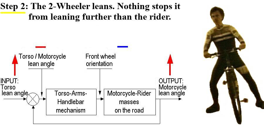
Step 2: The 2-Wheeler rapidly leans to its right due to the centrifugal force or the tire-ground contact patch’s left side movement.
When the 2-Wheeler’s lean angle is the same as the rider’s torso, the front wheel is oriented straight ahead. So there is no centrifugal force or tire-ground contact patch side movement generated to hold up the 2-Wheeler, which keeps on falling.
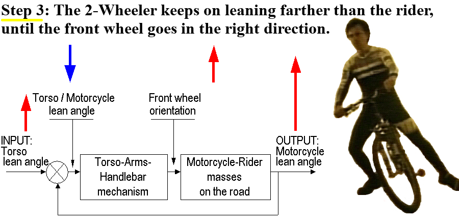
Step 3: The 2-Wheeler keeps on falling to its right. But the torso lean angle to the vertical stays the same because the rider does not want to fall further. So the 2-Wheeler keeps on falling to the right further than the rider’s torso, which orients the front wheel towards the right through the Torso-Arms-Handlebar mechanism (TAHm). Finally, this front wheel orientation lets the 2-Wheeler turn to its right and generates a centrifugal force that holds up the leaning rider and 2-Wheeler in a curve.
Note that at high speeds, the gyroscopic counter-reactions are strong and may flex the arms and elbows. So the rider may feel that he pulls or pushes on the handlebar according to the Countersteering technique. At such speeds, the Countersteering technique and the Body Leaning CountersteerS theory are quite similar. But the Body Leaning CountersteerS theory adds and explains that it is the torso lean angle that unconsciously starts and ‘cleverly’ controls the push-pull actions on the handlebar, through all the chain of events when going into a turn.
2.4 The Body Leaning CountersteerS (BLCs) theory is based on Scientific Principles and on Servomechanism Theory
2.4.1 Mechanical Engineering Thesis:
a) 1974-Mechanical Engineering Thesis:
This theory was introduced in a Mechanical Engineering Master Thesis, by Pierre Ethier back in 1974, at Laval University, Quebec City. The thesis presented a mathematical modeling of the 2-Wheeler-and-rider system, based on this theory.
>- Link to the 10.6 MB PDF version of this thesis: Dynamique des véhicules à deux roues et modifications les rendant plus sécuritaires https://corpus.ulaval.ca/entities/publication/38f1aea6-fab0-4252-ae9d-d934dae1eeac
>- Link to the 535 kB PDF version of the 1979 to 2019 corrections to this thesis: Erratum_02768_20190830.pdf https://corpus.ulaval.ca/server/api/core/bitstreams/434fec6f-6053-4dc1-b832-b83f8e250390/content
>- Link to the 584 kB 02768_Annexe.zip file containing the EXCEL file Calcul des constantes.xlsx https://corpus.ulaval.ca/bitstreams/655fb610-c0d6-43f1-9501-28b1df9b826f/download
All three documents are in French but are straightforward and can be understood.
b) The General Approach of this Mechanical Engineering Thesis was that:
>- Five masses were considered: (1) the rider’s torso-head, (2) the chassis, (3) the front-fork-handlebar-headlight, (4) and (5) the two wheels, each considered as a torus. The rider’s arms weight was partly integrated with the torso-head and partly with the front-fork-handlebar-headlight.
>- Holonomic, non-holonomic and Lagrangian Equations were derived for these masses.
>- The TAH Mechanism equations establishing the relation between torso-lean-angle-from-chassis to front-wheel-orientation were established, considering (a) elbows straight or rigid arms, and (b) hands on the handlebar in a line crossing the front fork rotating axis, which was representative of the studied motorcycle geometry, (c) torso leaning laterally right-left, (d) and no torso twisting (with one shoulder going backward while the other goes forward).
>- Simplification of the equations to small angles was done the latest possible. And Laplace transforms were used to derive the Transfer Function expressing the OUTPUT variable 2-Wheeler-Lean-to-Vertical, as a function of the intermediate variable Torso-Lean-to-2-Wheeler-Chassis.
>- Closed-loop servomechanism theory was used to derive the final Transfer Functions expressing OUTPUT as a function of INPUT variable Torso-Lean-to-Vertical-Plane, in both cases of the 2-Wheeler WITHOUT and WITH hands on the handlebar, the latter following the Torso-Arms-Handlebar Servomechanism hypothesis (The torso lean orienting the front wheel in the opposite direction through semi-rigid arms).
>- The parameters of a 1968 100cc Yamaha YL1A motorcycle were introduced in the equations, and minimum stable speeds determined, WITHOUT and WITH hands on the handlebar.
>- All mathematical derivations were done “by hand”, the old fashion way. And calculations of these minimum stable speeds were all done using a simple Hewlett Packard hand-held 10-Memory calculator.
>- Computer simulations were then made using the analog part of an early 1970’s analog-digital hybrid computer: A Heaviside Step Function was fed as INPUT (simulating the rider suddenly leaning to an angle to the vertical). A printout was then obtained of the OUTPUT in both cases WITHOUT and WITH hands on the handlebar, and at 16, 32, 64 and 130 KPH (10, 20, 40 and 80 MPH).
c) The Conclusions were that:
>- Minimum stable speed WITHOUT and WITH hands on the handlebar were close to what was observed, respectively 19,5 KPH (12.1 MPH) and 12,4 KPH (7.73 MPH), as reported in Dynamik23 section 2.2 Minimum stable speed calculations WITH and WITHOUT hands on the handlebar
>- In the case WITHOUT hands on the handlebar and as speed increased, rider sideways lean affected less the motorcycle lean to vertical, which was and can still be observed on all motorcycles.
>- In the case WITH hands on the handlebar and as speed increased, rider sideways lean controlled faster the motorcycle lean to vertical, which was and can still be observed on all motorcycles. AND the motorcycle leans more than the rider in a steady-state curve (as in a circle), as was NOT expected at first, which forced an error search for a few months, but which is now well understood and exposed as Step 3 when going into a turn, as presented in Dynamik23 section 1.3 Three steps when going into a turn
>- And equations would gain to consider flexible arms and torso, as measured on real moving vehicles… Which is still a valid conclusion as discussed above.
d) Excel Spreadsheet Constants Calculation:
>- Since calculations were done by hand which makes them hard to verify, these calculations were put in an Excel spreadsheet, so they can be verified and modified if desired.
>- Back in 1974, there were no largely accepted vehicle parameter conventions. So this spreadsheet can be used to translate to more accepted parameter designations.
e) Past, present and future research:
>- Not knowing how to treat how the rider controls the handlebar, research of the last decades has largely been concentrated on (a) modeling the bicycle and motorcycle systems WITHOUT hands and the handlebar, or (b) considering that the rider’s brain acted perfectly to control handlebar torque-steer in just the right amount for the 2-Wheeler to follow an intended path on the road, and (c) studying the effect of the Eigenvalues of the mathematical models, in search of ways to control unstable modes leading to shimmy and wobble.
>- Future research could certainly concentrate on modeling 2-Wheelers WITH hands on the handlebar, according to the present Body Leaning CountersteerS (BLCs) theory, and considering that the arms are flexible and the rider may exaggerate control of the handlebar (as the PID control of a servomechanism would do).
f) SAE paper:
The Society of Automotive Engineers paper SAE Paper 2000-01-3565 (SAE like “SAE 10W30” engine oil) was also published. It presented this theory in a simplified manner at the Motorsports Engineering Conference of November 2000 in Dearborn, Michigan.
2.4.2 Understanding the hidden steering servomechanism of the Body Leaning CountersteerS theory:
a) Servomechanism theory and diagram:
The Torso-Arms-Handlebar mechanism is a key part of a hidden Servomechanism.
So Servomechanism Theory, which is part of the more general Control System Theory, is essential to understanding this Torso-Arms-Handlebar theory.
The figure below shows a typical servomechanism diagram. Electrical and Mechanical engineers use them a lot to describe Closed-loop control systems:

Essentially, the Torso-Arms-Handlebar mechanism constitutes a key component of a non-obvious ‘follower’ steering servomechanism.
The following step-by-step reasoning explains more:
b) General block diagram with INPUT and OUTPUT:
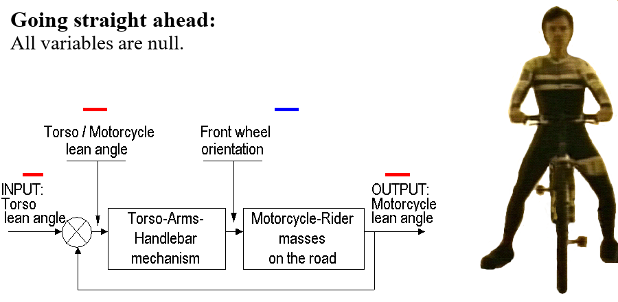
The new Torso-Arms-Handlebar theory considers that the rider uses his torso lean angle to control the 2-Wheeler lean angle according to the block diagram shown below, where:
– The INPUT is the rider’s Torso-lean-angle-to-the-vertical. The rider keeps his torso straight up to go straight and leans his torso to the right or left in order to go right or left.
– The OUTPUT is the right-or-left 2-Wheeler-lean-angle-to-the-vertical.
c) But where does the Torso-Arms-Handlebar mechanism fit in?
On the general block diagram above, the INPUT or Torso-lean-angle-to-the-vertical does not directly control the Torso-Arms-Handlebar mechanism of the image below. So what controls it, what’s the input to it?
It rather is the Torso-lean-angle-to-the-2-Wheeler that controls the Torso-Arms-Handlebar mechanism, since it is this lean angle to the 2-Wheeler that makes the arms push-pull on the handlebar.
 The INPUT or Torso-lean-angle-to-the-vertical (magenta color) may be 15 degrees to its right, but if the OUTPUT or 2-Wheeler-lean-angle-to-the-vertical (blue color) is 10 degrees also to its right, the final Torso-lean-angle-to-the-2-Wheeler (red color) is only:
(15 – 10) = 5 degrees = (INPUT – OUTPUT)
Thus, it is the INPUT (magenta) minus the OUTPUT (blue) that is fed into the Torso-Arms-Handlebar mechanism.
d) So the INPUT minus the OUTPUT is fed into the Torso-Arms-Handlebar mechanism:
This can be added to the diagram as follows:

Thus unknowingly, the rider on his 2-Wheeler acts as an [Error Detector] between the INPUT and the OUTPUT and feeds the [Torso-Arms-Handlebar mechanism] with the Torso-lean-angle-to-the-2-Wheeler (INPUT minus OUTPUT).
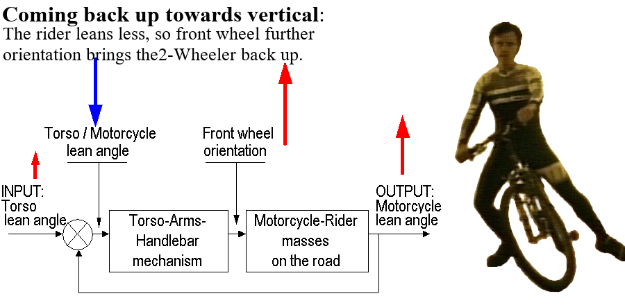
e) Finally, the Torso-Arms-Handlebar mechanism controls the Front-wheel-orientation, which acts directly on the [Rider plus 2-Wheeler masses on the road], to control the OUTPUT or 2-Wheeler-lean-angle-to-the-vertical:

f) Value change-over-time of the servomechanism variables:
The images below relate to the above section 1.3 Three steps when going into a turn. The arrow heights represent the angle value of the main variables of the steering servomechanism:
2.4.3 Which Torso-Arms-Handlebar geometries work best or worst:
a) One of the worst Torso-Arms-Handlebar steering geometry:
Road and road-racing bicycles have ‘Drop’ or ‘C’ shape handlebars and even ‘handlebar extensions’ that mount in the center of the handlebars.
The Torso-Arms-Handlebar geometry of such ‘Drop’ or ‘C’ shape handlebars is such that a small torso leaning angle generates a large orientation of the front wheel. So when the rider leans his torso in a curve, the arms flex due to the gyroscopic counter-reactions of the front wheel. Thus, the 2-Wheeler servomechanism reacts slowly, sluggishly and imprecisely to the rider torso’s controlling inputs.
The central ‘handlebar extensions’ are even worst since the torso leaning translates into no front wheel orientation. The bicycle steering then only relies on the torso weight leaning right or left, and corresponding front wheel gyroscopic reactions, to turn right or left. These reactions are strong and ‘fast’ at high speeds, but not at ‘low and medium’ speeds.
b) Another worst Torso-Arms-Handlebar steering geometry:
As a general rule, if the rider’s elbows can flex, the torso leaning will only sluggishly cause an opposite orientation of the front wheel. This is like inserting a slowing ‘Time Constant’ in the open loop of the steering servomechanism. (In fact, the servomechanism block diagram and the mathematical model would certainly benefit from adding the flexibility of the arms, which is a factor that becomes increasingly more important as speed and gyroscopic counter-reactions increase.)
On a motorcycle where the rider is too tall for the motorcycle or sits forward too much, the rider’s elbows may be flexed as much as 90 degrees and are then even more ‘flexible’. An example of the rider sitting forward too much is on a motorcycle where the rider sits forward closer to the wind screen, in order to get more protection against rain or cold. Another typical and potentially more problematic example, because the vehicle is more heavily loaded, is on a touring motorcycle where the rider sits forward more, in order to leave room for his rear passenger. Things work well going straight on a highway due to the front wheel’s strong gyroscopic stability, but emergency maneuvers will certainly be slow and imprecise.
Curiously, ‘custom’ motorcycles with handlebars higher than the riders head, have an acceptable steering geometry: When the rider leans to one side, he solidly pulls on the opposite steering handle, so that the front wheel reacts instantly. However, a first problem with these motorcycles rather comes when the front wheel extends far forward. The extended wheelbase then generates weaker centrifugal correcting forces. This translates into higher minimum stable speeds WITH and WITHOUT hands on the handlebar, with the associated difficulty riding at slow speeds in town or in parking lots. A second problem with these motorcycles is that the small front wheel is associated with a small front brake that do a poor job at stopping the motorcycle.
c) Some of the best Torso-Arms-Handlebar steering geometries:
The best steering Torso-Arms-Handlebar steering geometries are the ones of mountain bikes and off-road motorcycles: The large straight handlebar insures that torso leaning induces precise and fast front wheel orientation with little elbow flexing. Such Torso-Arms-Handlebar steering geometry are very well adapted to the job of riding slowly around obstacles on the ground like rocks or trees.
2.4.4 Where does the steering servomechanism damping come from:
The servomechanism block diagram shows that we are dealing with a follower servomechanism where the INPUT or 2-Wheeler lean angle to the vertical, follows the OUTPUT or torso lean angle to the vertical.
This block diagram also shows that as soon as an error between INPUT and OUTPUT exists, a signal is generated to correct the OUTPUT. The problem is that if the corrective signal is very strong, the OUTPUT will be corrected but may overshoot the INPUT. Another corrective signal will then be generated in the opposite direction… So the OUTPUT will oscillate without stabilization. The servomechanism will then be said to be ‘pumping‘. This simply explains why all servomechanisms must have a certain amount of damping. But in the case of our steering servomechanism, there is no mechanical hydraulic damper or electrical resistance damper slowing down the right-left leaning motions of the 2-Wheeler chassis. It is thus surprising that this steering servomechanism is so stable (Excluding the ‘wobble’ effect of the front fork, which is something different).
Thus, there must exist some other sort of ‘dynamic’ damping stabilizing the steering servomechanism. Fortunately, it’s possible to get an idea of where it comes from:
An error between INPUT and OUTPUT generates a front wheel orientation that generates a centrifugal force that corrects the OUTPUT. At first look, this correcting force seems directly and solely proportional to this error between INPUT and OUTPUT, but it is not: For example, consider as a starting condition the rider and 2-Wheeler being at certain steady state angles to the vertical in a constant curve. The rider may lean further, so the 2-Wheeler will follow the lean angle after a short time and turn in a shorter radius on the road. Thus, if the speed is kept constant, the 2-Wheeler will be turning faster around its vertical axis. (A motorcycle at 15Km/h turns faster around its vertical axis while turning in a parking lot than while turning in a long slow curve on a highway at the same speed.) Its rotational kinetic energy around this axis will have increased, compared to the starting condition.
It is precisely this increase in rotational kinetic energy that will have slowed down and ‘dampened’ the leaning motions of the 2-Wheeler. This dampening is ‘dynamic’ and it’s not an energy loss through heating as for a conventional hydraulic damper or electrical resistance damper. It rather is an energy ‘transfer’ from one form to another. So the generated ‘correcting’ force is not simply proportional to the error between INPUT and OUTPUT. It’s also reduced proportionately to the rate of change in lean angle (its speed), which corresponds to a dampening function.
More to it, servomechanism people talk about PID systems, which stands for Proportional-Integral-Differential.
The Proportional part means that as soon as there is an error between the Output (like the 2-Wheeler chassis lean angle to the vertical) and the Input (like the rider’s torso lean angle to the vertical), there is a correction signal generated to reduce this error, and this correction signal is a proportional to the error. So it’s not like an On/Off thermostat that turns heating on at maximum capacity. It’s more progressive and reduces chances of ‘pumping‘ explained above.
The Integral part means that if there still is a small remaining error between the two angles, this small error will be mathematically ‘integrated‘ and will result into a correcting signal that will progressively increase to eventually reduce this small error. Although not always the case, an example can illustrate this mechanism with elevators: If you watch carefully an elevator door at the bottom, you may see the door open and the elevator floor that has not arrived to its full stop and that slowly adjusts to a final stop with elevator floor and level floor at the same height. Another example concerns the turbine speed of an hydroelectric dam: This speed may control the electric frequency (50 or 60 Hz) of many electric clocks in a country. So this speed must be precise and it must correct itself if the electric loads of the country have slowed down the turbine, in order to avoid clocks misalignments.
As for the rider’s torso and the 2-Wheeler angles, there is no Integral part. But as for the global system (see the following section hereunder) of the rider and 2-Wheeler in the road environment, there definetly is an Integral part: Even if the error is very small between where the rider wants to go and where the rider-vehicle are really going, this error will result in the rider seeing that they are going out of the road. So the rider will correct his torso lean angle and he will avoid going into the ditch.
This last example supports the idea that when riding a mountain bike, you identify a line where you want to go, and you ‘through’ or lean your body in that direction. And when you are racing, you continually update this line and continually update your body leaning to go in that direction.
The Differential part means that if the error between Output and Input, suddenly changes, the correcting signal will be mathematically ‘diffentiated‘ and will result in a correcting signal that will be increased more than proportionally, relulting in a faster correction.
Here again as for the rider’s torso and the 2-Wheeler angles, there is no differential part. But here again as for the global system (see the following section hereunder) of the rider and 2-Wheeler in the road environment, there definetly is a Differential part: If for example the rider-vehicle are crossing a bridge like the Quebec City bridges across the St. Lawrence River, under a strong North-East (Nordest) or South-West (Suroît) side-wind, they may be subject to a disturbance when passing supporting pillars. When the rider suddenly feels this disturbance, the suddenness can make him react strongly to it, more than proportionnaly.
2.4.5 The global system including the rider and 2-Wheeler in the road environment:
A global servomechanism block diagram can also be identified and modeled: The rider sees an image of the environment in front of him. In this image, he ‘throws’ his torso towards a point on the road in front of him. The torso lean angle to the vertical controls the 2-Wheeler lean angle to the vertical and the front wheel orientation, according to the steering servomechanism explained above. So the 2-Wheeler keeps on moving forward but also turns on the road towards that point in front of him. This changes the image seen by the rider who ‘throws’ his torso towards a different point on the road in front of him, which modifies his torso lean angle and the front wheel orientation…
This global servomechanism easily explains that if a misalignment exists in the 2-Wheeler construction, if the rider sits sideways or if there are road imperfections, all these errors are corrected by this global servomechanism: If the 2-Wheeler does not go in the right direction, the rider will throw his body towards the right point in front of him, so the 2-Wheeler will change course towards this point. The image in front will change again, the rider will again throw his torso … until this right point is attained. It’s exactly the same as in a car where the driver aims at a point in front on the road.